01Precision path
All-electric
For repeatability, clean production and process sequences that depend on precise simultaneous motion.
Select a plastic injection molding machine from the part data and mold envelope, then define the drive, clamp, injection unit and production-cell scope the project actually needs.
No model recommendation before the part, mold and output target are understood.
A machine photo can ground the project conversation, but it cannot identify the right configuration by itself. Use the visible cell only as context for mold access, material handling, utilities, operator tasks and the evidence still needed.
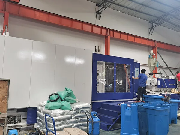
Explore the machine architectures that shape precision, mold access, cycle sequence, utilities and production-cell design.
For repeatability, clean production and process sequences that depend on precise simultaneous motion.
For versatile production where a broad processing window, robust operation and capital fit matter.
For larger molds and parts where mold access, clamp architecture and efficient floor space matter.
For insert loading, overmolding and production cells built around operator or robot access.
“How many tons?” is not a complete brief. A defensible recommendation connects the molded part, the tool, the process and the whole cell.
Geometry, projected area, resin, shot weight and cosmetic or tolerance requirements.
External size, tie-bar clearance, thickness, daylight, ejector and core-pull needs.
Cavity count, runner system, cycle target, annual volume and uptime expectations.
Power, cooling, material handling, robot interface, layout and destination standards.
Speed / repeatability / auxiliaries
Large molds / integration / process stability
Versatile processing / cost per part
Precision / mold protection / traceability
Access / handling / safe loading
Clean configuration / process control
A useful proposal explains mold fit, injection-unit logic, cell scope and acceptance checks so engineering, operations and procurement can review the same project.